
Structural PU foam support
The method uses structural polyurethane foam as part of a defined keyhole support and restraint geometry.
Evidence
HydroFoamer evidence focuses on the engineering basis, measured installation control, auditable as-built records and the project-specific validation needed for restrained buried composite pipe installation.
The evidence question is not whether foam exists. It is whether the installed system can provide controlled support, restraint and verification in the project context.
The method uses structural polyurethane foam as part of a defined keyhole support and restraint geometry.
Foam behaviour must be assessed against project-specific loads, support geometry, installation sequence and long-term assumptions.
HydroFoamer is focused on restrained buried pipelines where support, bends, movement and coupling behaviour are central design questions.
The support geometry, native backfill interaction and pipe system determine how loads are distributed around the installed pipe.
Long-term behaviour requires engineering review. HydroFoamer does not remove the need for project-specific material and design validation.
Measured pipe position, alignment and coupling deflection help connect the installed condition to the engineering model.
“For pipeline installations carried out using the HydroFoamer restrained installation method, where pipe alignment, movement, and settlement are controlled and verified throughout the length of the pipeline during installation; the designer may consider the nominal joint deflection capacity of the pipe system, as the restrained installation conditions significantly reduce the uncertainty factors typically associated with conventional buried pipe installation.”
Why this matters
Conventional buried pipe installation carries uncertainty from trench geometry, bedding quality, compaction, pipe movement, settlement and site execution. HydroFoamer changes those assumptions by controlling and verifying pipe alignment, movement and settlement during installation.
This recognition matters because it links the construction method to the design assumptions behind buried composite pipe systems.
HydroFoamer is not only a material substitution. It is a controlled installation method with evidence attached to it. The evidence should answer practical questions before the installed condition is hidden.
Measured position records help confirm where the pipe sits before and during support installation.
Alignment checks support field control before conditions are hidden by backfill.
PGMS-enabled checks can support review of angular position and coupling geometry.
Measured installation control is intended to reduce uncertainty from pipe movement and settlement during installation.
Records can connect survey, foam application, QA/QC and installation hold points.
PGMS, Leica / total station integration and BIM / digital twin handover can create auditable as-built records.
Evidence is useful when it reduces a decision-maker's uncertainty. It should connect the engineering model, the field condition and the handover record.
Alignment, position and coupling geometry records help connect design intent to the installed condition.
Foam application records and field checks should show the support sector and keyhole geometry used on the project.
Movement and settlement observations help distinguish controlled installation from assumptions made after backfill.
Imported aggregate, native backfill, foam volume and spoil movement should be traceable to the project comparison.
QA/QC records should identify checks before foam application, before backfill and at as-built handover.
Engineering, geotechnical, contractual and regulatory validation remain attached to the actual route and pipe system.
Published evidence materials
These documents show HydroFoamer moving through field application, academic discussion and structured safety review. They are evidence inputs for project-specific review, not universal design standards.
Regulator-facing briefing
A HydroFoamer information deck prepared for a meeting with NVE on the use of PU foam around composite pipe routes, with emphasis on safety assessment and documentation.
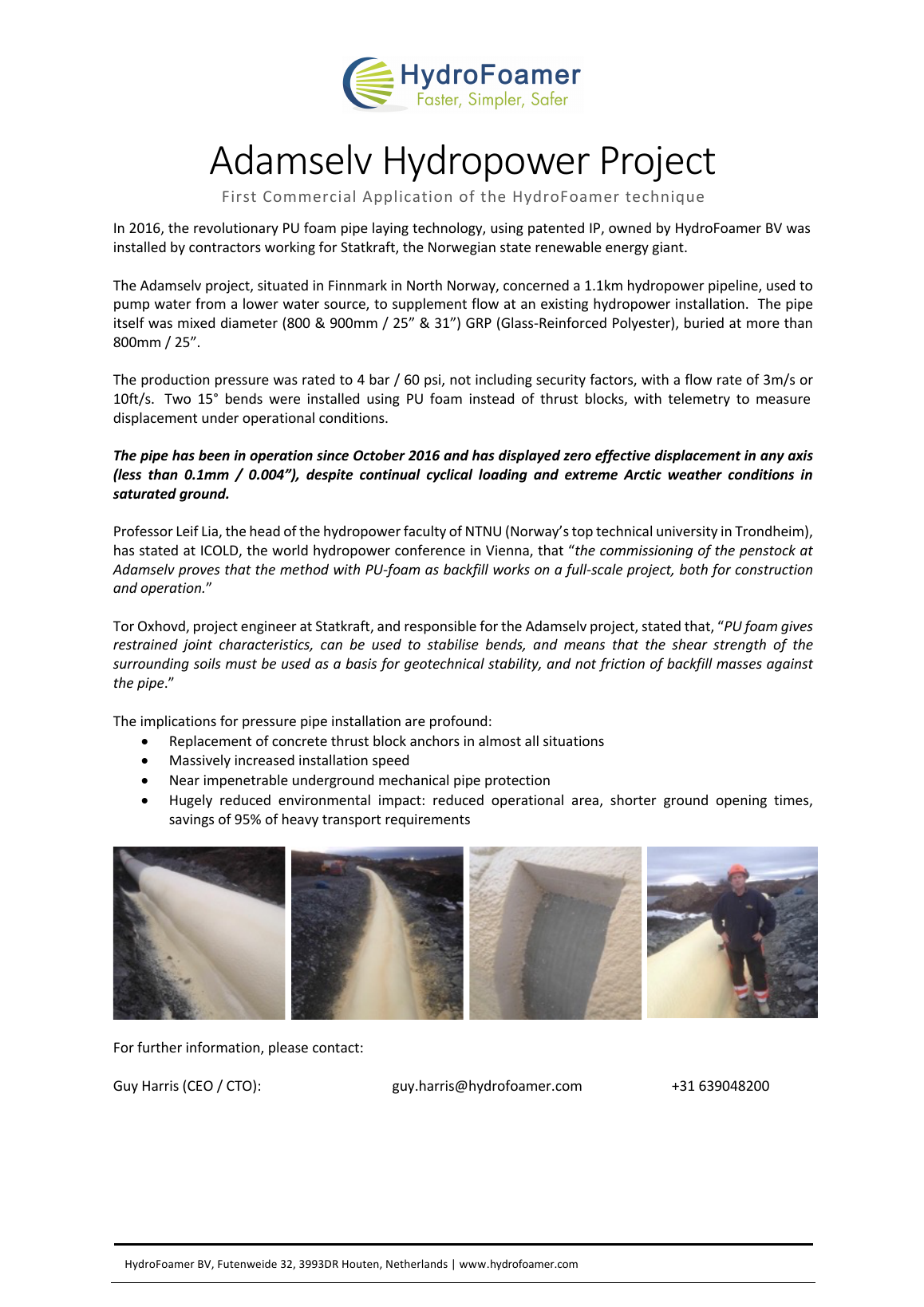
Field history
A historical project note on the 2016 Adamselv / Lille Måsevann installation in Finnmark, describing a full-scale composite hydropower pipeline context and monitored bends installed with PU foam.
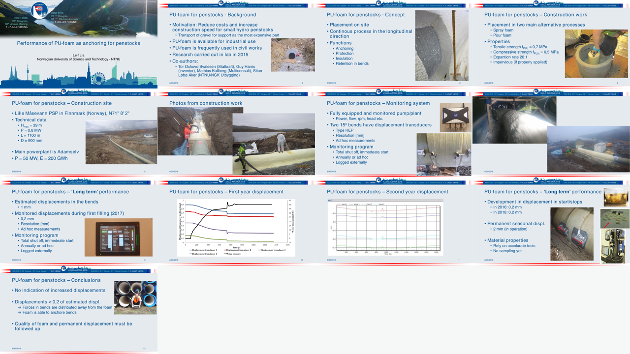
Academic dissemination
Professor Leif Lia's NTNU presentation to ICOLD 2018 placed PU foam anchoring for penstocks in an international dam and hydropower engineering forum.
The NVE briefing is evidence of structured technical engagement; it should not be read as regulatory approval. Adamselv, ICOLD and NVE materials remain context-specific and do not replace detailed engineering, geotechnical, contractual or regulatory validation for new projects.
Project engineering example
This technical-plan excerpt from Eikeelva shows a project-specific trench cross-section for a HydroFoamer installation in Norwegian mountain terrain.
The drawing matters because it shows the method becoming an engineered installation detail: pipe position, sidefill, overfill, sprayed PU foam support and construction geometry are treated as one system.
This is a project-specific engineering example, not a universal trench standard. Future projects require their own engineering, geotechnical, contractual and regulatory review.
View Eikeelva trench section PDF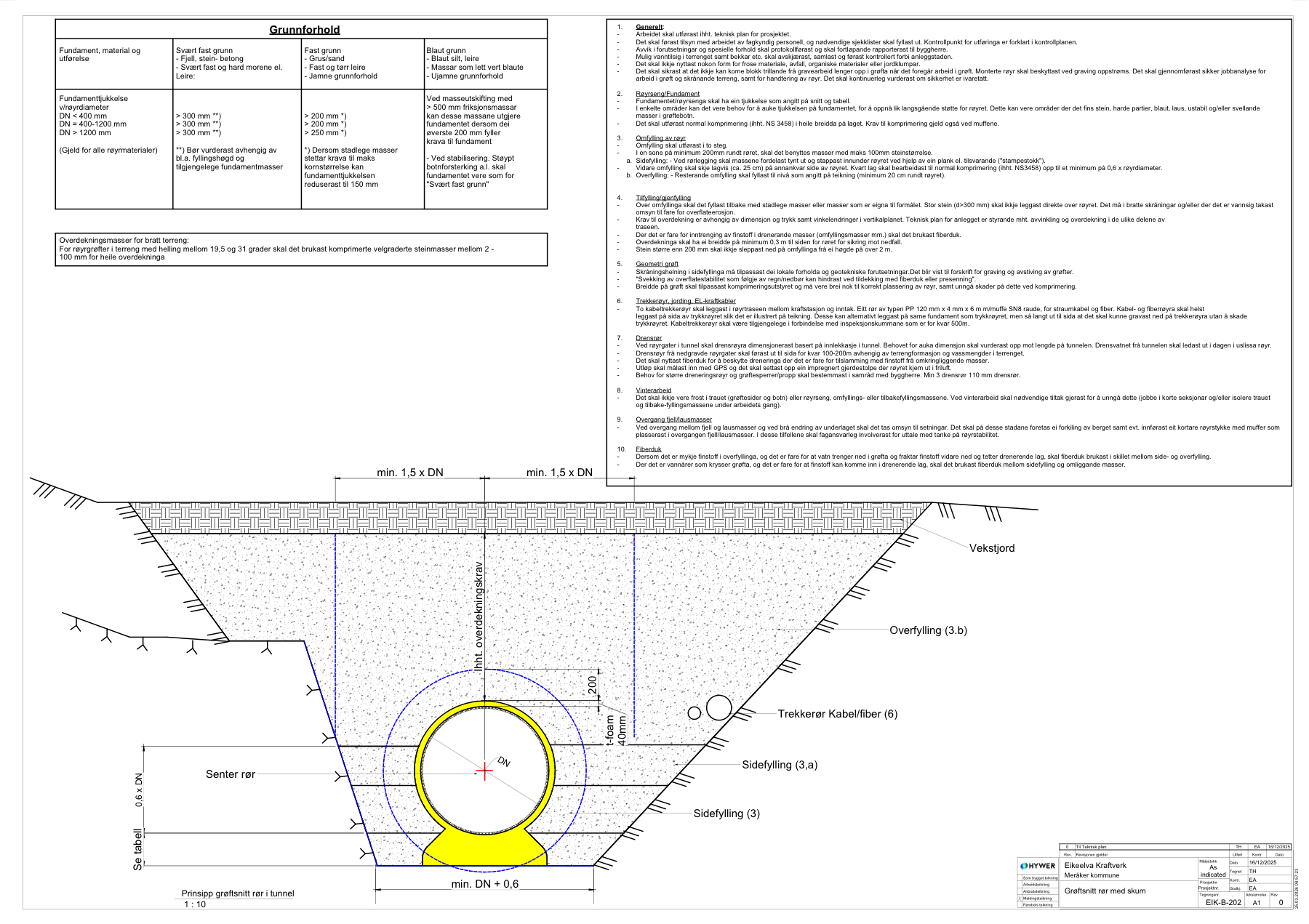
Project and test evidence
Project and test evidence should be linked to the actual pipe system, trench geometry, soil context, installation method, foam design and acceptance requirements. Published materials support the evidence pathway, but new projects still require their own qualification.
Ask for the evidence pathway relevant to your pipe system, installation constraints, qualification needs and commercial scenario.